Case Study
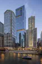
Rags to Riches: How Chicago's 111 West Wacker Finally Got Built
Text from CTBUH 2015 New York Conference
Introduction
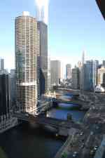
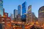
In 2005, Chicago-based developer Teng & Associates released plans for a tower to be built at 111 West Wacker Drive, situated on a highly visible stretch of the Chicago River lined with architecturally notable buildings, with landmarks such as 333 West Wacker, the Merchandise Mart, and Marina City counted among its immediate neighbors. Citizens and visitors alike place high regard on the architecture of Chicago, as is evidenced by the many Architecture-themed boat tours which ply the waters of the city throughout the day.
The Teng’s and Associates plans called for a new 92-story tower for this highly visible riverfront site, a building which would house a Shangri-La Hotel and Residential condominiums, along with retail and parking at its lowest levels.
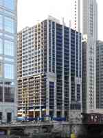
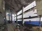
By the time the 2008 financial crisis hit, the building concrete superstructure had reached the 25th floor. When attempts by the developer to secure bank financing failed, work stopped, and the building at 111 West Wacker sat as a highly-visible half-built concrete eyesore in the heart of the city.
In 2011, the developer Related Midwest purchased the site with the intent of converting the incomplete structure into a residential tower that would fit within the context of world-class architecture along the River. The challenges were many: addressing nearly 4 years of inactivity at the site through several freeze and thaw seasons; shifting project goals from hotel to residential use; and modifying the structure to support a new 60-story design. All of this had to be done in a way that wouldn’t compromise the marketability of the new building.
The Site and Existing Conditions
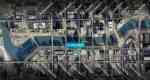
The project is situated on a half-acre parcel at the southwest corner of Wacker Drive and Clark Street, in the heart of Chicago’s central business district and directly overlooking the iconic main branch of the Chicago River. The site consisted of an existing 25 story concrete shell with 4 levels of below grade structure. With the earlier program, the ground floor served as the hotel and residential lobby, with some associated retail spaces. The 2nd through 11th floor were dedicated to above grade parking, with the 12th through 24th encompassing the hotel program. The 25th floor was slated to become the amenity level for the hotel, with infrastructure such as a swimming pool shell already in place. The 1st and 2nd lower level floors were dedicated to hotel function space. A grand two-story connection between lobby and lower level 1 served to tie a future ballroom with the ground floor. LL3 and LL4 were designed as parking, with access from LL1 off of Lower West Wacker Drive.
The structure already in place was designed for a very specific approach to the overall tower design. Large, robust columns measuring 5’-3” by 10’ ran along the river frontage of the site, following a slight curve imposed on the structure to satisfy the original design. Springing from this robust base, a triangular tower was planned, which transferred a great deal of its shear load down through these West Wacker-fronting piers. Ironically, given the fact that another 67 floors of tower were meant to land atop the already extant structure, given its triangular footprint, not all columns were designed and built to take a superimposed tower load. This deficit would have needed to be addressed by the structural engineering team once a final tower footprint was established. All told, nearly 40,000 cubic yards of concrete was already in place. The amount of resources, in material, embodied energy, and shear dollars, meant a hard look at issues and opportunities to reuse this shell was warranted.
A team from Wiss, Janney, Elstner Associates was engaged by the owner to evaluate the existing conditions of the work already in place. The entire structure was exposed to the elements for nearly 4 years. Some components of the structure would have to be replaced. Most components would need some level of remediation but could still be used as part of a repurposed building. Elements of the exterior cladding, including unitized curtainwall, unitized stone, and unitized metal panels were housed off site at outdoor storage yards. Most of these materials had suffered from prolonged exposure and could not be reused as fabricated. Components were broken down and recycled for their scrap material to be reconstituted as other products or building materials.
Early Analysis, Design and Construction
A key component of early research on the structure was understanding what was in place, not just from the overall design aspect, but also in relation to the ways and means components of the construction process. Leave outs for cranes and material lifts, never documented on design drawings, represented potential opportunities to rework floors and create new connections without the added cost of cutting and framing out new holes in slabs. Though all openings were considered, a few proved useful to help the design team rethink programmatic possibilities.

In particular, the existing material lift, having run from Lower Wacker to the top of the existing structure, would prove useful as part of the future parking elevators (previously parking was to be limited to users of the building; with a considerably smaller population in the new design, overflow parking could be rented for public use, if a means to provide outside public access could be found). The location and size of this leave-out fit the bill nicely, given its location to the south/east of the site, close to the West Wacker street frontage.

Many slab openings in the hotel floors were of a nature not appropriate to residential use. Our proposed mechanical system, for example, did not marry with the fan coil system that the hotel had been designed for. Many small openings (duct and pipe chases, toilet and shower drains) needed to be filled. This left the task of introducing new openings for things such as heat pumps, washer/dryers, kitchens, and relocated bathrooms, to the design and construction team to resolve within the context of in-place and undocumented existing conditions. The first 25 floors of construction were executed as conventional two-way way flat plate concrete, with a slab thickness of 9” at parking, and 8” at hotel floors. Any new penetration through existing slabs needed to avoid, as best as possible, any rebar buried in the concrete.

An analysis with the structural engineer lead to establishing certain rules and criteria: only one line of rebar can be cut by any core drilling. If a number of cores needed to be drilled that could result in breaking more than one bar, an x-ray would need to be done to document rebar locations and coordinate core drilling to leave bars continuous and undisturbed. Throughout the 12-24th floors, shaft locations were laid out and x-rays done to document rebar locations. Core drilling then commenced with confidence that rebar would remain untouched and intact.
The core structure of the project, comprised of shear walls girding elevators, stairs, service and support spaces, measured nearly 58’ x 71’. This proved to be exceedingly large, with many spaces left unused from the original design. In addition, large 3-story voids were created along the south/west corner where useable hotel program could not be realistically located (this portion of the site was buried by the adjacent Lasalle Wacker building to the west and the 203 North Lasalle Building to the south). The project team reviewed these spaces with careful consideration of potential uses compared with selective, and costly, demolition. Core spaces in the podium were characterized and tracked based on size and location.
The three story corner volumes could be utilized for many of the podium-centered systems, including fresh and exhaust air machinery, and in particular the building transformer vault, located at the highest tier of the podium, allowing ready access up and down the building to feed power to all floors.
By using podium level spaces this way, the team began to sort the overall mechanical direction for the tower: the podium, with its opportunities with ready-built space, would contain its own mechanical systems, while the new tower above would tackle its mechanical needs through a core approach that made sense with the new program. The challenge was how to marry this new program laid onto a new tower footprint with its own unique structural needs, superimposed onto a shell with entirely different elements.
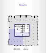
After studying the structure, the best solution involved moving the tower out towards the front of the site in order to capitalize on the best river views; keeping those core elements that cannot move (e.g. elevators) and moving those that can (e.g. stairs); laying out a normative column structure that works with residential planning; and creating a transition between the two that works structurally (columns, shear walls, core), mechanically (transformer location, MEP systems), and architecturally (unit planning, cladding, and overall aesthetic consistency). All of this needed to come together at the transition between existing and new. The most complicated elements were the ones that were most unique to the project, and the ones that would be built first, 25 floors in the air.
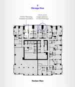
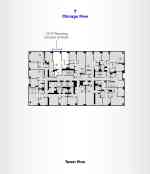
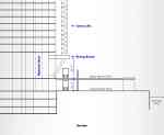
The module spacing for the hotel below was based on a room demising dimension of 13’-9 ½” center-to-center. A normative demising dimension for the sort of residential product being contemplated was 12’-0” center to center. These dimensions yielded column spans of roughly 22.5’ clear, readily achievable with flat plate construction. But with the oversized piers of the existing construction, column “centerlines” reached 27’-7”, while the smaller columns for new construction above would be in the range of 24’ on center. It was decided that instead of continuing columns through to the new tower portion above and having to compromise new units with the old spacing, a structural transfer would be introduced at the top of the 25th floor.
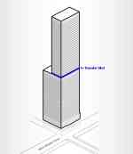
Transfer beams were considered, but given the sheer number of transfers, it was decided to go to a transfer mat, 5’ thick, to reconcile the two spacings. Given the volume of concrete involved, the transfer mat would be executed in two horizontal pours. The first pour, 24” in thickness, once cured to achieve its design strength, would support and act as the bottom formwork for the second pour. In addition to traditional rebar reinforcing, the mat slab would utilize post-tensioning tendons, with 2 layers of PT strands, each running in two directions, one set of which connecting upper and lower pours, allowing the two pours to act as a single slab once tensioned into its final loading condition.
Typical section of transfer mat
01
/
00
Elevators and trash chutes could not be moved. However, stairs, electrical closets, low voltage wiring, and mechanical elements would transfer to a new core, one that allows a more efficient footprint, but more importantly, one that would allow pushing the tower, originally kept 8’ back from the street wall by in-place elements, forward to front along West Wacker. This forward push allowed units, especially at the corners, to take full advantage of a site that offers spectacular views east and west along the Chicago River.
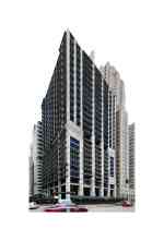
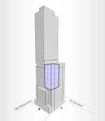
Architecturally, it was important for the design team to create a unified building form, one that would encompass the entire structure as one complete and cogent idea, unencumbered by the change in design necessitated by the break in construction, program, and ownership. Once the structure could be modified to embrace the new column spacing with new unit layouts, and a simplified and more efficient core, the approach to cladding the building could be applied. Many material palettes were investigated, including stone, terra cotta, and metal panel. An all-glass scheme was chosen as the overall cladding system, a custom curtain wall using primarily reflective glass. With a taut glass skin as a base, an incised element was introduced, a “ribbon” of non-reflective glass, darker in appearance, wending its way up and around the structure in a continuous move around all four elevations. This ribbon helped create project specific moves on the entirety of the mass of the building in a manner that reinforced the vision of the building as a whole.

As an architectural element, the ribbon offered an opportunity to create breaks at major elements of the building. Aesthetically this helped create the highlight zones where programs like the amenity floor would be located. Urbanistically, these breaks would tie into the street wall, registering the continuity of buildings along the River and cornice lines from our immediate neighbors, respecting the in-place rhythm along this highly visible frontage.
These breaks also allowed discontinuities to be masked within the overall volume of the tower. Given the module break from units below and above the amenity floor, the 10’ deep incised ribbon at the north face of the amenity level allows a transition from the larger 13’-9 ½” to smaller 12’ module with a physical separation from one to the other. Only the north east corner, once carefully worked out, would run continuously up and down the entire building using the same curtainwall modulation throughout this zone.

Construction wise, these ribbons contributed to a crucial aspect of scheduling the project. The amenity ribbon would allow the introduction of a new starter for the curtainwall system, hidden by the use of a carefully detailed “zipper” connection which allowed out-of-sequence curtainwall installation to be executed. Curtainwall typically wants to be installed from the bottom up. Given that 25 floors of the building were already in place, the contractor wanted to start as soon as possible with enclosing in-place floors to continue with interior fit-out. These “zippers” would allow curtainwall installation to occur first at two, and ultimately in three stacks at the same time. This meant more crews could complete the enclosure in a much shorter timeframe than conventional bottom-up sequencing.
The custom curtainwall system was fabricated overseas and shipped to the site as unitized panels. The design team worked with the fabricator to create a modulation of 6’ wide units, which could readily fit on the construction hoist and be maneuvered on the floor with relative ease. Two basic module types for the upper portion of the tower were developed: a 6’ wide picture window, and a combined 2’ operable next to a 4’ fixed unit. This 4’ unit would vary from a spandrel application (covering a column or heat pump) or a vision lite. Variations on the 2’, 4’ panel and the 6’ picture window were arrayed around the building, with the occasional interruption of a “ribbon” unit.
The ground floor condition offered another opportunity for means and methods efficiency to be realized. The unusual situation of having a partial shell of a building already in place, especially the very robust columns at the river frontage, meant a new approach to locating a crane would be possible. The previous crane slab leave-outs, on the south east corner of the site, were situated for the triangular tower as originally planned. These previous leave outs would now overlap the newly proposed tower footprint. A new tower crane location needed to be chosen. Given the tight space constraints and barring the possibility of cutting 29 new holes in the existing slabs, careful consideration of precious street frontage needed to be reviewed for a crane located on West Wacker Drive or Clark Street. A novel approach, proposed by the concrete subcontractor, placed the tower crane atop a concrete “diving board” located 30 feet above the Upper West Wacker roadway. Raising the base of the crane allowed utilization of a drive and unloading path under the crane itself, thereby freeing up valuable logistics real estate. In addition, the existing material hoist started at the B1 level, allowing loading from Lower Wacker Drive as well. With these elements in place, construction activities could be fed from two logistics points.

The Lobby Entrance
The lobby entrance is framed by two over-sized metal panels depicting an abstract treescape. The panels were manufactured in painted plate aluminum by Zahner.

Western panel system.

Different panel options were studied with varying amounts of solidity.

The selected design depicts branches in an abstract form.

The "bird connection."

Stacked panel system prior to installation.
01
/
00
Sustainability and the City
The developer maintains a nationwide presence, and has committed across all markets to green and sustainable building practices. With the careful review of existing as-built conditions and creative design approaches, the vast majority of the 40,000 cubic yards of concrete already in place was utilized and expanded upon for the continuation of the new tower program. Low-e glass with a mix of insulated spandrel panels makes for an efficient building envelope. The entire building, though mainly residential, is designated as a smoke free environment to improve the indoor air quality. As a testament to these efforts, the building has been awarded LEED Gold Certification by the U.S. Green Building Council.
But perhaps most importantly, the shell of the original construction, having sat prominently on the magnificent frontage of the Chicago river for nearly four years, was in all respects a real manifestation and constant reminder of the recession that began in 2008. The site wasn’t merely an eye sore; it was a daily reminder of the situation played out across the country. Projects stalled, and the economy was lagging. The site could have been demolished and started anew, wiping away its most recent history. But the transformation of this stack of concrete floors meant something different, that something was changing, that the situation was improving, not just for this one project, but perhaps for the entire industry within the city of Chicago. The changes were apparent, and once begun, were quick. Construction began in earnest in December of 2012, with substantial completion in July of 2014. Within one year, new concrete was added and the entirety clad with a new skin, bringing this site back into the fold of the city, making it again a part of the fabric of Chicago’s daily life.
Market Acceptance
The project was widely accepted by the market, experiencing unprecedented leasing success. As of December 2014, OneEleven was 80 percent leased and 75 percent occupied, averaging more than $3.60 per square feet – 25 percent above original projected rents for the project. This record-breaking pricing and brisk absorption rate was unprecedented in Chicago.
The building went under contract for sale when it was just 70 percent leased. Ultimately, the sale of OneEleven paid all former lienholders of the project, as well as investors. The building was built for $180 million and sold in January 2015 for $328 million, setting a record for the highest price-per-unit paid for an apartment building in Chicago at $651,000 per unit.
01
/
00